BookTitleOkabe Product Catalog
- page
- 49/134
This page is an overview of Okabe Product Catalog on page49
Move to the page after second(s).
Now go to the page by clicking "Open the e-Book" button.
This page is an overview of Okabe Product Catalog on page49
Move to the page after second(s).
Now go to the page by clicking "Open the e-Book" button.
Okabe Product Catalog
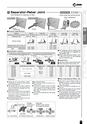
A B C G TemporaryConstructionConcreteRebar Work Formwork CivilEngineering① Set the product to a rebar and tighten the nut witha ratchet.(Tightening torque: Approximately 20N・m)② Screw a Separator into the nut for connecting the Separator, and adjustthe in-and-out dimension of Separator against the wall thickness.D19・D22D13・D16ナットD25・D29セパグリップセパレーターセパグリップセパレーターD19・D22D13・D16ナットD25・D29セパグリップセパレーターセパグリップセパレーターD19・D22D13・D16ナットD25・D29セパグリップセパレーターセパグリップセパレーターD19・D22D13・D16ナットD25・D29セパグリップセパレーターセパグリップセパレーターParalleldirectionPerpendicularS size M size directionSeparator-Rebar JointJoint hardware for separator & rebar● Tighten the nut at approximately 1.96kN・cm (200kgf・cm). Be sure to use the productwithin the allowable load.● The allowable load for an angle in directionsother than perpendicular and parallel directionsshould not exceed the allowable load in theperpendicular direction.● Note that the numerical value of the allowableload is the strength of the main body oft h e p r o d u c t , a n d d e f o r m a t i o n d u e t oarrangement condition of reinforcing bars isnot taken into consideration.● When using the product M or MW, place a rebarin the position indicated in Fig. 1.Cautions● Note that if the screwing length ofseparator is short (11.5mm or less forW5/16 and W3/8), prescribed strengthcan no bt secured.● Check the product for damage, etc., beforeuse.● Do not use the product for any purposeother than its intended purpose.● When installing the product, confirmits specifications and precautions, andhandle the product with sufficient care.● The allowable load is applied when Okabeseparator is used, it will not be guaranteedwhen other separator is used.◆When using Separator-Rebar Joint◆Product specification◆Installation methodFig. 1 Types M and MW Fig. 2 Separator welding direction ○ Welding allowed × Welding not allowedNotch sideNotch side Parallel to rebar: AllowedAt an angle: Not allowedFlat sideFree direction onthe flat sideFlat side◆When welding Separator...● Weld separator before the product is attachedto rebar.● If separator is welded to rebar, the initialtorque may be reduced because of weldingheat. Therefore, be sure to tighten the nutagain when the assembly has cooled downafter welding.● Do not fill the air-bleeding hole when weldingseparator.Product Applicable rebar diameter Separator size Weight (kg/pc) Weight (kg/case) Quantity (pc/case) PackingType S8D13・D16(D10)W5/16 0.164 16.4 100 CaseType S9 W3/8 0.162 16.2 100 CaseType SW ? 0.146 14.6 100 CaseType M8D19?D29W5/16 0.239 12.0 50 CaseType M9 W3/8 0.237 11.9 50 CaseType MW ? 0.226 11.3 50 CaseType LW D32?D38 ? 0.223 11.2 50 CaseProduct Type S Type SW Type M Type MW Type LWApplicable reinforcing bar diameter D13?D16(D10)D13?D16(D10) D19?D29 D19?D29 D32?D38Separator size W5/16・W3/8 ? W5/16・W3/8 ? ?Product shapeTightening torque kN・cm (kgf・cm) 1.96(200)Allowable load kN(kgf)Parallel direction 4.90(500) ? 4.90(500) ? ?Perpendicular direction 2.94(300) ? 2.94(300) ? ?◆Application(Installation)● Foundation formwork, pressure plate formwork● Slab outer wall of box culvert, etc.● T he allowable load for welding typeis not described as it depends onthe welders’ skill.● W hen using Separator-Rebar JointS with D10, use it in the allowableload of 2.94kN or less.(Parallel)*(Perpendicular) (Parallel) (Perpendicular)* In case of the perpendicular direction, avoid the notch side. (See precautions.)Welding type Non-welding typeFirmly grips the reinforcing barEasy installationImprovedconcrete fillingpropertySeparatorSeparator-Rebar JointNutSeparator-Rebar JointSeparatorProduct No. B10-052047